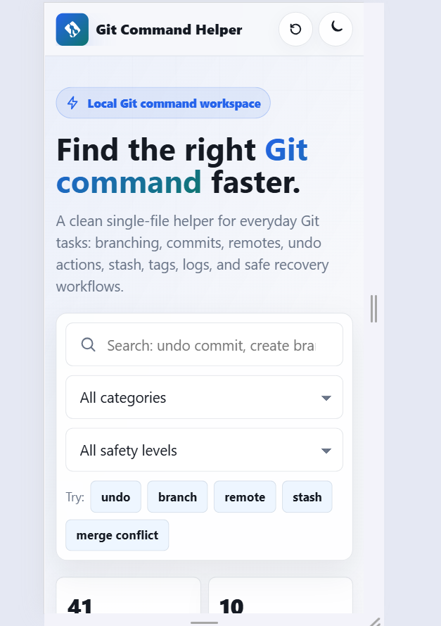
Show List

Structural Diagrams

Class Diagram:

  • Represents the static structure of a system, showing classes, attributes, operations, and relationships.

UML Class Diagram References:


Visibility
UML has the following types of visibility:

public (+)
package (~)
protected (#)
private (-)

Relationship Names
Names of relationships are written in the middle of the association line.

Multiplicity
How many objects of each class take part in the relationships and multiplicity can be expressed as:

Exactly one - 1
Zero or one - 0..1
Many - 0..* or *
One or more - 1..*
Exact Number - e.g. 3..4 or 6
Or a complex relationship - e.g. 0..1, 3..4, 6.* would mean any number of objects other than 2 or 5

Purpose of Class Diagrams
Shows static structure of classifiers in a system
Diagram provides a basic notation for other structure diagrams prescribed by UML
Helpful for developers and other team members too
Business Analysts can use class diagrams to model systems from a business perspective


Object Diagram


Provides a snapshot of specific instances of classes and their relationships at a particular point in time.

Purpose of Object Diagram

In the analysis phase of a project, it is common to construct a class diagram to delineate the system's structure. Subsequently, a series of object diagrams may be generated as test cases to validate the precision and comprehensiveness of the class diagram.

Prior to crafting a class diagram, an object diagram may be devised to uncover details about particular model elements and their connections. This process may also serve to exemplify specific instances of the classifiers that are essential for the project.


Example:
Sample class diagram

Corresponding Object Diagram

Component Diagram


Component diagrams show the dependencies between the logical and physical components of a system with the interfaces that each component requires and provides and their ports.
Interface

Symbols with a full circle at the end denote provided interfaces, indicating that the component offers this interface. This "lollipop" symbol serves as a shorthand representation for the realization relationship of an interface classifier.

On the other hand, symbols with only a half circle at the end, often referred to as sockets, signify required interfaces. In both instances, the name of the interface is positioned near the corresponding interface symbol.

  • Provided Interface: Represents an interface that the component offers or provides to its environment. It is depicted with a full circle at the end.

  • Required Interface: Represents an interface that the component expects or requires from its environment. It is illustrated with a half circle at the end.

Port Ports are depicted by a square positioned along the border of a system or component. Frequently employed to expose the required and provided interfaces of a component, ports play a crucial role in system representation.


In a UML component diagram, a port serves the purpose of providing a point of interaction between a component and its environment. It represents a gateway through which the component can offer or require interfaces.

The main purposes of a port in a component diagram include:

  1. Exposing Interfaces: Ports help in exposing the interfaces that a component provides or requires. Provided and required interfaces are often associated with ports.

  2. Inter-Component Communication: Ports facilitate communication between components. They define how components interact with each other, allowing for the exchange of information and services.


Deployment Diagram


A UML deployment diagram illustrates the arrangement of runtime processing nodes and the components residing on them. These diagrams belong to the category of structure diagrams utilized for representing the physical aspects of an object-oriented system. Typically, they are employed to depict the static deployment view of a system, specifically focusing on the hardware topology.

When to Utilize Deployment Diagram Which existing systems must the newly incorporated system interface or integrate with? What level of resilience does the system require (e.g., redundant hardware in case of system failure)? Which entities and processes will establish connections with or interact with the system, and what will be the methods of interaction? Which middleware, encompassing the operating system and communication methods and protocols, will the system employ? Which hardware and software will users directly engage with (PCs, network computers, browsers, etc.)? How will the system be monitored post-deployment? What level of security does the system necessitate (requires a firewall, physically secure hardware, etc.)?

Objectives of Deployment Diagrams
They illustrate the configuration of the run-time system.
They record the hardware employed to execute the system and the connections among various hardware elements.
They portray physical hardware components and the communication pathways connecting them.
They serve as a tool for strategizing the system's architecture.
They also provide utility in documenting the deployment of software components or nodes.

Example:


    Leave a Comment


  • captcha text