Show List
Behavioral Diagrams
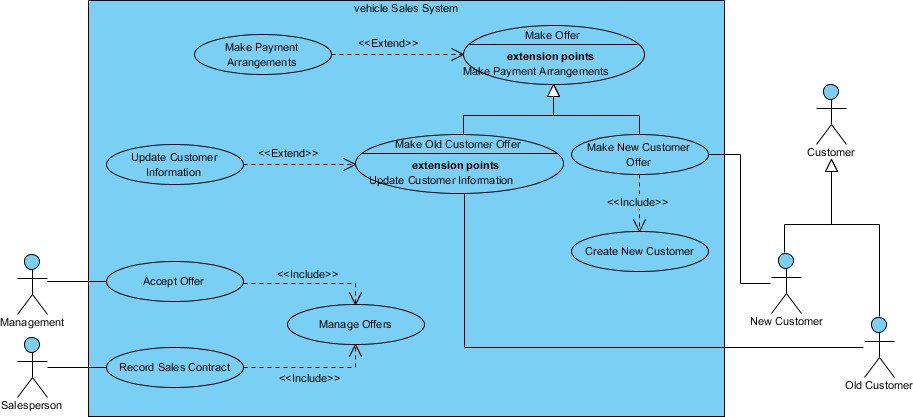
Use Case Diagram
A UML use case diagram serves as the principal representation of system requirements for a new software program. Use cases articulate the anticipated behavior without specifying the precise methods of achieving it.
Purpose of use case diagram
Use case diagrams are commonly crafted in the initial phases of development, and individuals frequently utilize use case modeling for the following objectives:
Define the system's context Document the system's requirements Verify the architecture of a system Guide the implementation process and generate test cases Formulated collaboratively by analysts and domain experts
Symbols and notations
Actor:
Someone interacts with use case (system function).
Named by noun.
Actor plays a role in the business
Actor triggers use case(s).
Use Case:
System function (process - automated or manual)
i.e. Do something
Each Actor must be linked to a use case, while some use cases may not be linked to actors.
Extend:
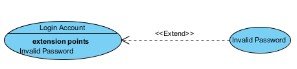
Indicates that an "Invalid Password" use case may include (subject to specified in the extension) the behavior specified by base use case "Login Account".
Depict with a directed arrow having a dotted line. The tip of arrowhead points to the base use case and the child use case is connected at the base of the arrow.
Include:
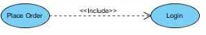
When a use case is depicted as using the functionality of another use case, the relationship between the use cases is named as include or uses relationship.
A use case includes the functionality described in another use case as a part of its business process flow.
A uses relationship from base use case to child use case indicates that an instance of the base use case will include the behavior as specified in the child use case.
Example:
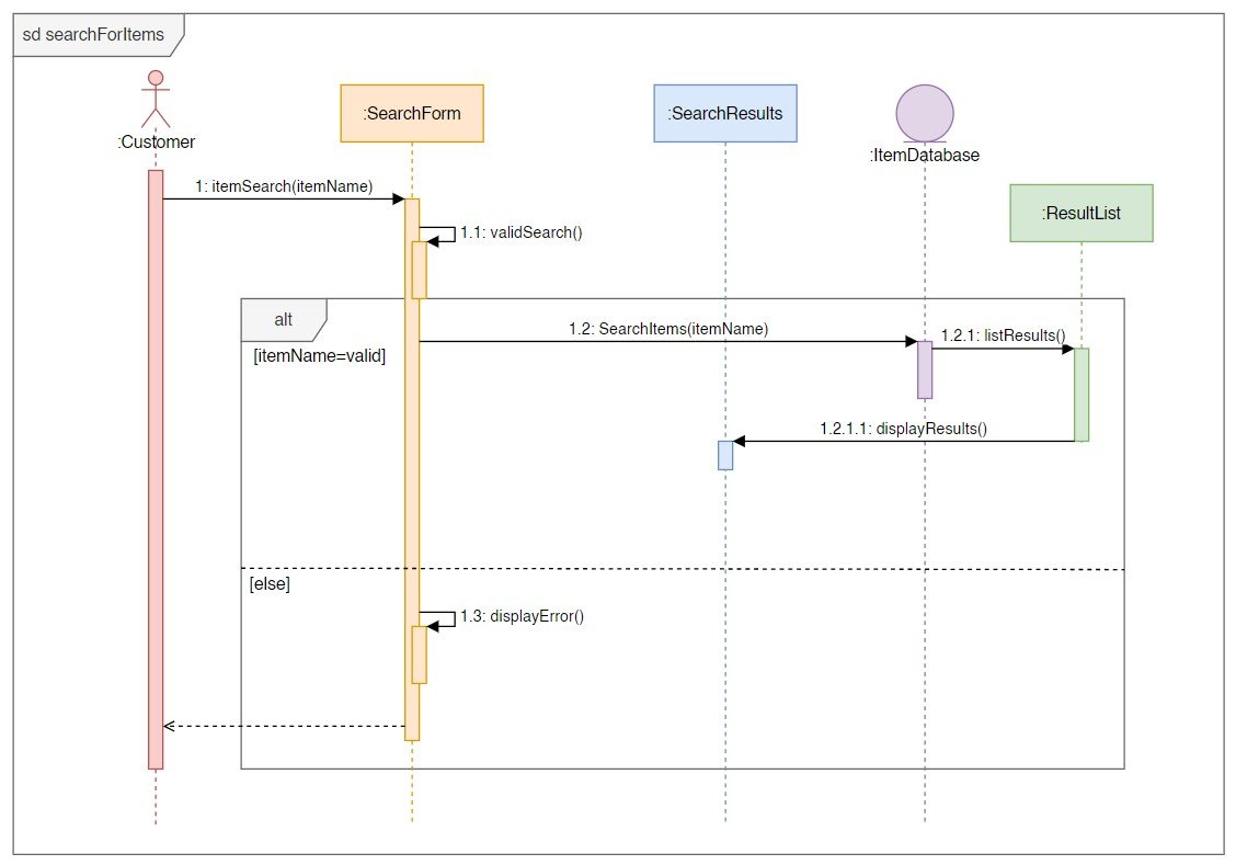
Sequence Diagram
Sequence Diagrams capture:
1 The interactions occurring in a collaboration that implements either a use case or an operation (instance diagrams or generic diagrams) 2. High-level interactions among the user of the system and the system, between the system and other systems, or between subsystems (sometimes referred to as system sequence diagrams)
Example:
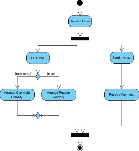
Activity Diagram
Activity Diagrams describe how activities are coordinated to provide a service.
Example:
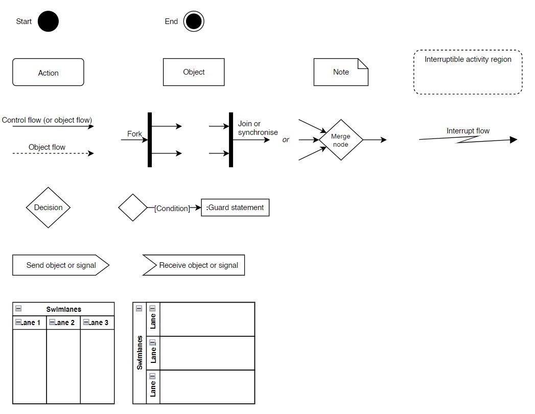
Notations:
Purposes of Activity Diagram:
- Recognize potential use cases by analyzing business workflows.
- Determine pre- and post-conditions (the context) for use cases.
- Diagram workflows between and within use cases.
- Illustrate intricate workflows in operations on objects.
- Elaborate on detailed activities through a high-level activity diagram.
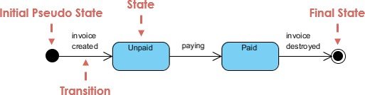
State Machine Diagram
UML State Machine Diagrams, also known as state diagrams, state machines, or state charts, depict the various states of an entity. These diagrams also illustrate how an entity reacts to different events by transitioning from one state to another.
Example:
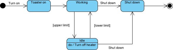
Notations:
Leave a Comment